
Bluetooth and an FPGA in 6 × 11.5 mm.
The S1 puts a Bluetooth 5.2 chip, an FPGA, battery charging and flash in one module for wearables and other small battery-powered devices. Connect a lithium cell and it runs.
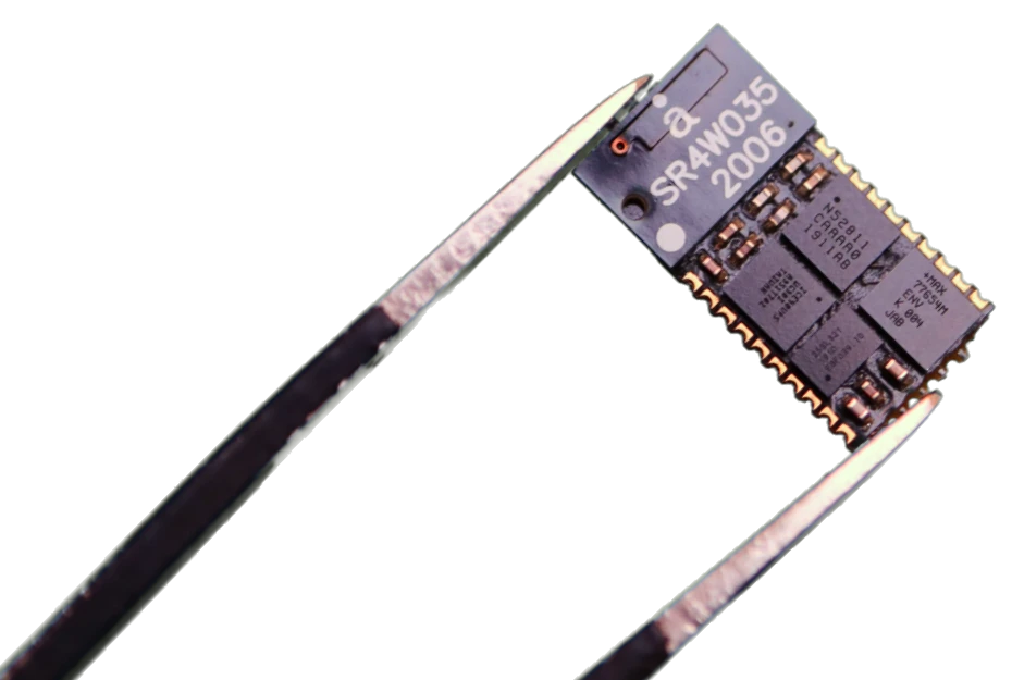
- Antenna built in
- nRF52811 Bluetooth 5.2
- MAX77654 LiPo charging
- iCE40 FPGA, 5k LUTs
- 32 Mbit flash
Four chips in one module.
A Nordic nRF52811 runs Bluetooth 5.2, Long Range and Thread. A Lattice iCE40 UltraPlus FPGA with 5k LUTs, 1 Mb of RAM and DSP blocks handles signal processing. A Maxim MAX77654 charges a LiPo cell and provides three adjustable rails. 32 Mbit of flash holds the FPGA image and your data.
- 8 FPGA IO, including I3C and a USB pair
- 2 nRF52 IO for the ADC or waking from deep sleep
- 3 adjustable rails, with buck-boost up to 5.5 V from one lithium cell
- Antenna, crystals and passives built in
- 6 × 11.5 × 1.6 mm, rated −40 to 85 °C
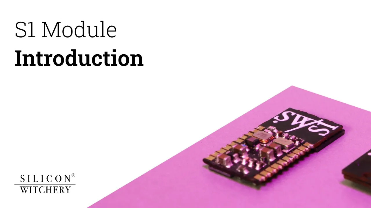
MicroPython or C SDK
from machine import PMIC, FPGA

# Configure the FPGA IO rail
PMIC.vio_config(1.8)

# Start the FPGA
FPGA.run()

# Read 256 bytes from the FPGA
rx = bytearray(256)
FPGA.read(rx)
Use MicroPython to explore your data and change code on the fly. Connect from your browser with our Web Bluetooth REPL.
MicroPython for S1void main(void) { // Initialize S1 base settings APP_ERROR_CHECK(s1_init()); // Configure power rails s1_pimc_set_vfpga(true); s1_pmic_set_vaux(3.3f); s1_pmic_set_vio(2.8f, false); // Reset FPGA and wake flash s1_fpga_hold_reset(); s1_flash_wakeup(); }
Use the C SDK for full control. It gives you a minimal starting configuration to build on.
C SDK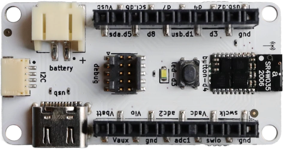
S1 Popout board
A development board with an S1 already soldered on, so you can start prototyping straight away.
- S1 Module soldered on
- Every IO broken out
- Qwiic and STEMMA QT port for plug-in I²C sensors
- JST battery connector, charged over USB-C
- 10-pin Cortex debug header, user button and LED
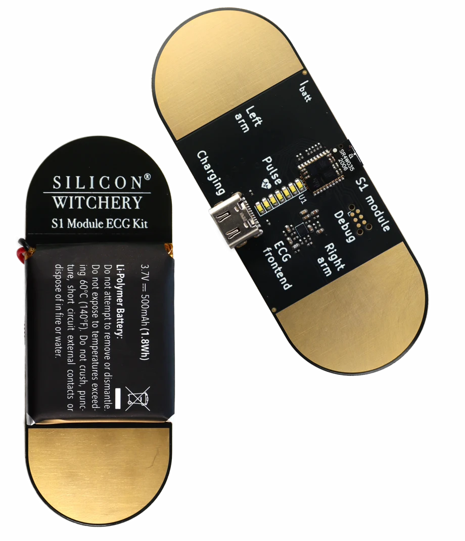
S1 ECG Reference Kit
An ECG analog front end and an S1 Module on one board. Use it to learn about heart health, research ECG algorithms, or start a new product. The design files and source code are open.
- AD8233 ECG front end with three probes, read by holding the board in both hands
- Built-in LiPo battery, charged over USB-C
- LED bar graph and a current measurement port
The engineers who built the S1 can build yours.
Silicon Witchery designed the S1. Our engineers can design the board your S1 solders onto, write its firmware and FPGA code, and take your product through certification. Or we can design your whole product from scratch.